Published: 24 października 2021
Classification of generator sets acc. to ISO 8528
Classification of generator sets acc. to ISO 8528
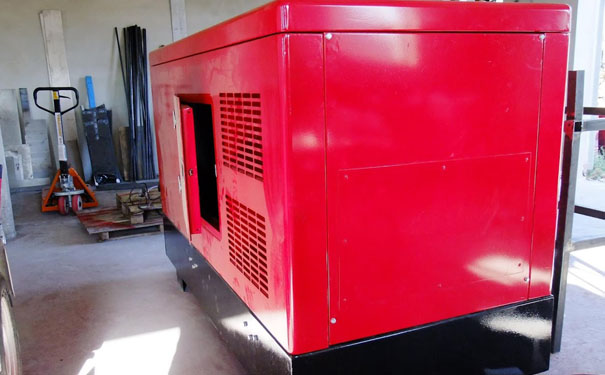
The PN-ISO 8528 standard refers to alternating current generating sets driven by an internal combustion piston engine, i.e. popular generating sets.
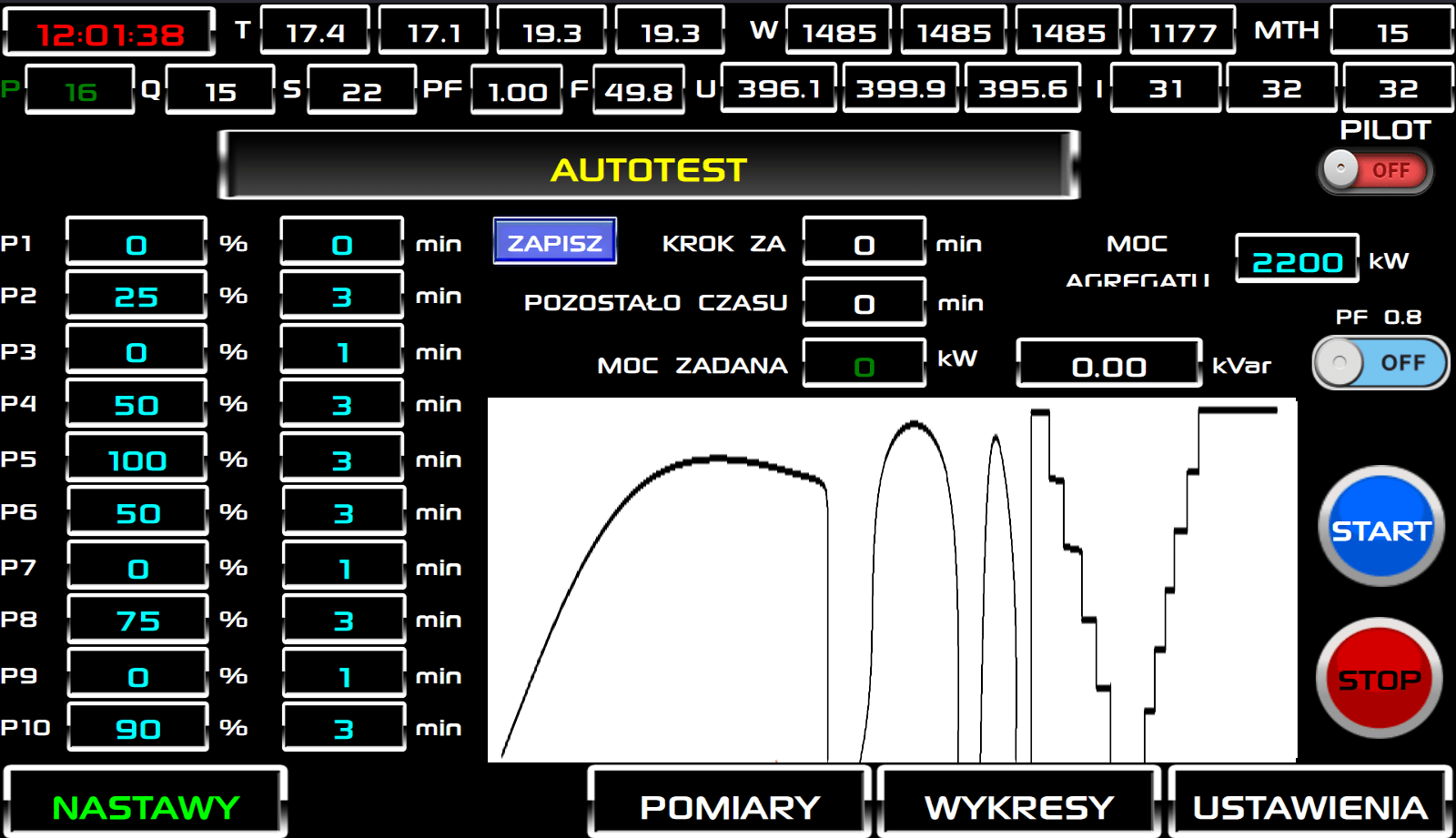
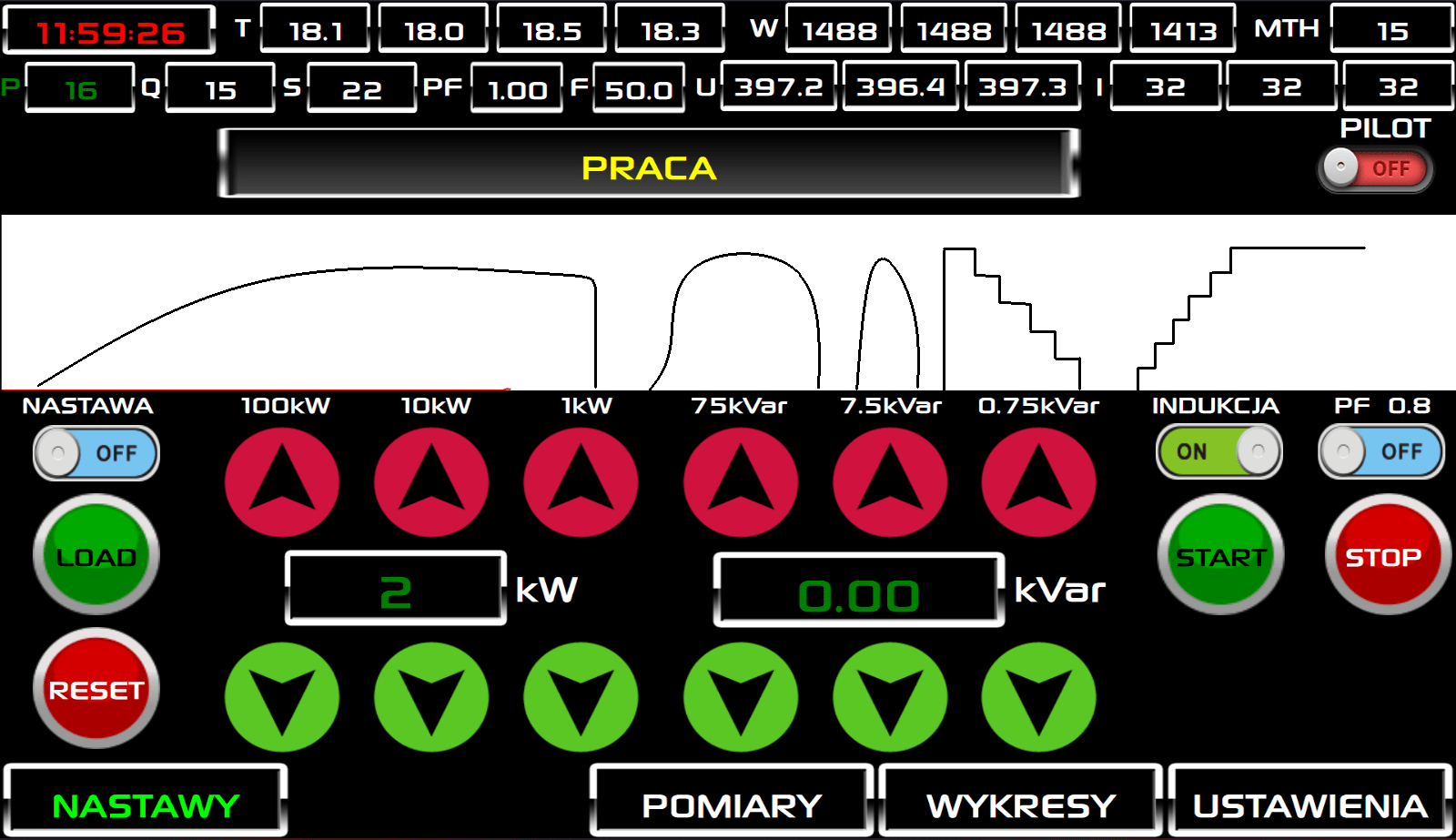
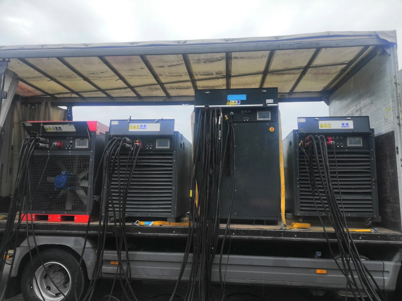
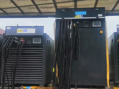
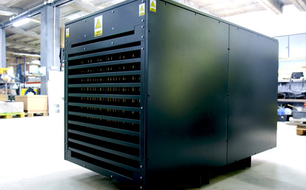
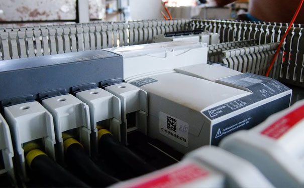
According to this standard, we have created a device that allows to test the operating parameters of power generators and classify them into specific groups.
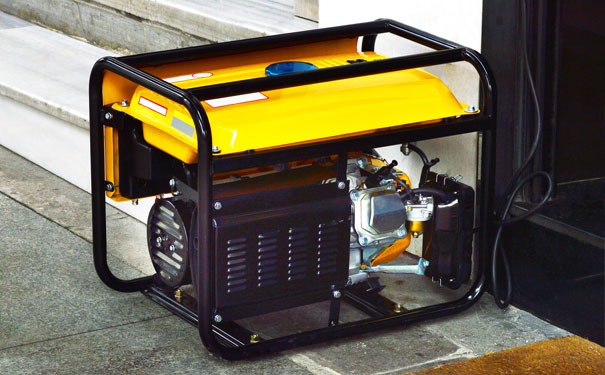
- Class G1 – The device meets the basic requirements for grid parameters in terms of voltage and frequency. Generators of this class can power lighting or electric heaters.
- Class G2 – The device provides a grid quality similar to that guaranteed by the public electricity network. In the case of load changes, temporary deviations from the nominal values of voltage and frequency are allowed. These units are suitable for powering devices such as power tools or electronics.
- Class G3 – The device provides a higher quality of electrical parameters compared to the public electricity grid. This type of generators is used when there is electronics in the building that are sensitive to the quality of power supply.
- Class G4 – The device meets the special requirements for the electrical network specified by the customer. Special-purpose devices supplying key infrastructure facilities, e.g. Data Center.
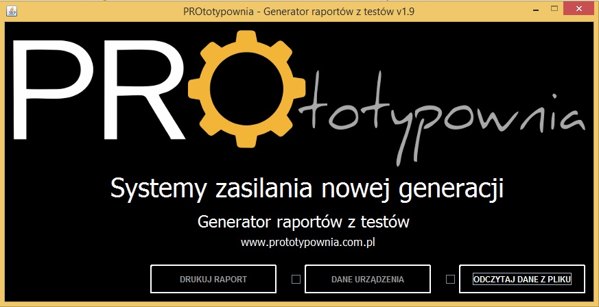
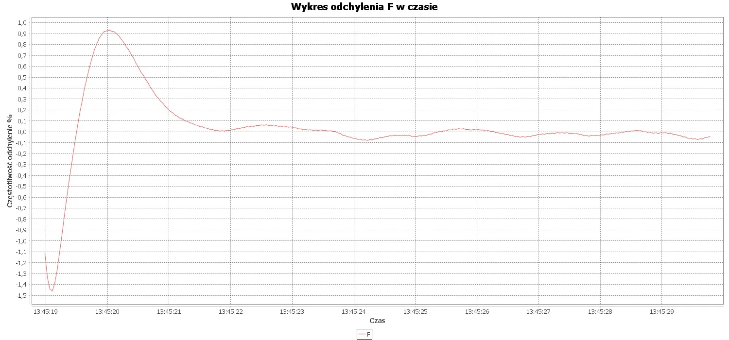
During the tests, the device saves measurements with a frequency of 0.04 s to ensure the highest quality of data for analysis. After the tests are completed, it is possible to generate an automatic report along with an analysis of the results.
Parametry sprawdzane podczas testów
| Parametr | Jednostka | G1 | G2 | G3 |
|---|---|---|---|---|
| Spadek częstotliwości | % | ≤8 | ≤5 | ≤3 |
| Pasmo zmian względnych wartości częstotliwości w stanach ustalonych | % | ≤2,5 | ≤1,5 | ≤0,5 |
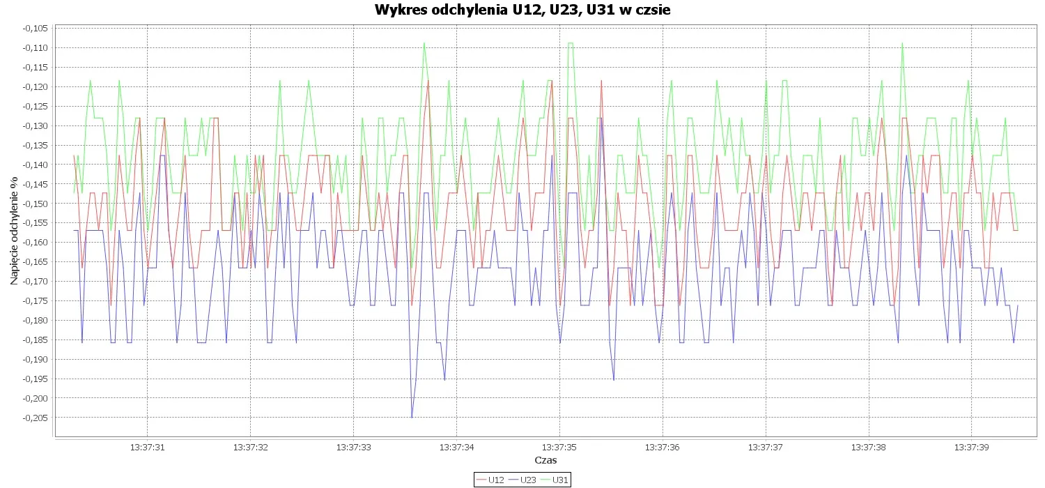
| Odchyłka napięcia w stanach ustalonych | % | ≤5 | ≤2,5 | ≤1 |
| Niezrównoważenie napięcia | % | ≤1 | ≤1 | ≤1 |
| Przejściowa różnica częstotliwości od częstotliwości początkowej – Nagły wzrost mocy |
% | ≤-15 | ≤-10 | ≤-7 |
| Przejściowa różnica częstotliwości od częstotliwości początkowej – 100% nagłego spadku mocy |
% | ≤+18 | ≤+12 | ≤+10 |
| Przejściowa odchyłka częstotliwości od częstotliwości początkowej – Nagły wzrost mocy |
% | ≤-15 | ≤-10 | ≤-7 |
| Przejściowa odchyłka częstotliwości od częstotliwości początkowej – 100% nagłego spadku mocy |
% | ≤+18 | ≤+12 | ≤+10 |
| Przejściowa odchyłka napięcia - Nagły wzrost mocy | % | ≤-25 | ≤-20 | ≤-15 |
| Przejściowa odchyłka napięcia - 100% nagłego spadku mocy | % | ≤+35 | ≤+25 | ≤+20 |
| Czas odbudowy częstotliwości | s | ≤10 | ≤5 | ≤3 |
| Czas odbudowy napięcia | s | ≤10 | ≤6 | ≤4 |